
From here Not from here Datum plane B Datum plane C Datum plane A True position Goodheart-Willcox Publisher Figure 8-9. Specifi cation of the correct material condition is relatively easy when the effects are clearly understood. One of the material conditions is optimum for any given design application. Effect of Material Condition Modifi ers The three material conditions applicable to position tolerances have distinctly different effects. If the measurements are not perpen- dicular, then an accurate check of the hole positions cannot be made. Because of angular varia- tion between datum features B and C, measurements made off the two surfaces may not be perpendicular to one another. Being able to remain in one coordinate system is unlikely when working off imperfect feature surfaces. When working relative to the datum reference frame, all measurements are in a single coordinate system. The exaggerated variations on the shown fab- ricated part indicate the importance of the datum reference frame. Depending on the magnitude of the part variations, dimensions extending from the datum reference frame could be signifi cantly different from dimensions extending from the part surfaces. The datum reference frame is a perfect coordinate system. All location measurements for the two holes are made relative to the datum reference frame, and not relative to the part surfaces. In a solid model where no dimensioned views are created, the hole locations relative to the datum reference frame are established by the digital data in the model. The hole pattern is dimen- sioned to locate it relative to these datums. The given part shows a position tolerance in which datum features A, B, and C are referenced. Dimensions are applied with consideration given to referenced datum features. Review Chapter 6 for additional information about datum reference frames. A datum reference frame provides a known origin and coordinate system for dimensions and toler- ances. The datum feature references establish the datum reference frame. This exception is explained in more detail later in this chapter.

Relationship to the Datum Reference Frame Position tolerances must include datum feature references except when the toleranced features act as the primary datum from which other features are located. There is no tolerance applied to the basic dimension itself the posi- tion tolerance is applied to the features. There would not be a difference because there is no tolerance accumulation on basic dimensions. There would be no difference in the true positions if both holes were dimensioned with base- line dimensions extending from the datum feature. Figure 8-8 shows two horizontal dimensions chained together to locate the true positions of the two holes. When the toler- ance is applicable at MMC or LMC, the surface of the hole must not violate the virtual condition boundary. The axis of the actual produced hole may be located anywhere within the tolerance zone.

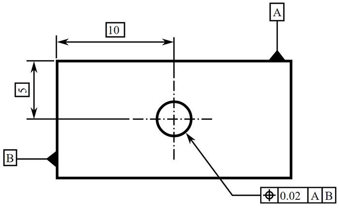
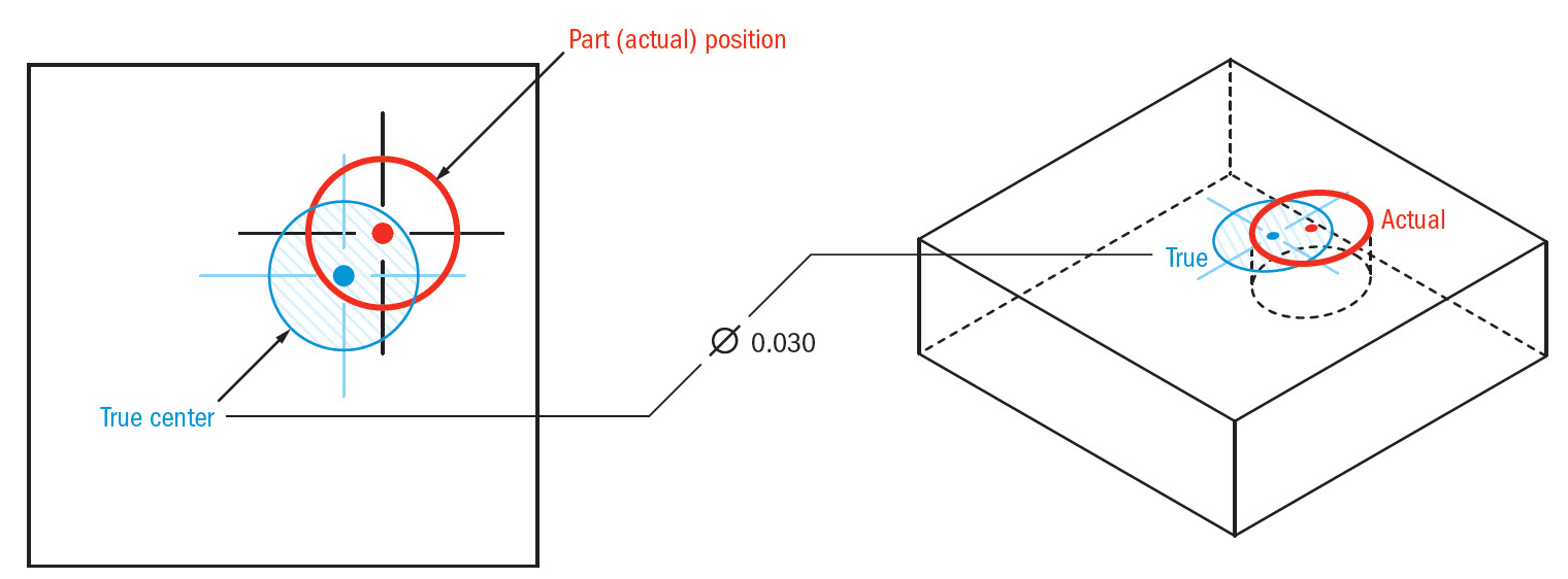
The true position is the as-designed location for the hole, the specifi ed position tolerance zone, and the virtual condition. There must always be an allow- able amount of position tolerance. Datum -B- will be something that aligns the part, lets say a side. So Datum -A- is the top flat surface (gaining 0 bonus). However, you add (Highest allowable tolerance-actual dimension) for each one. 006 + (highest allowable dimension-actual dimension). However, a true position does not indicate the hole is required to be perfectly located. The actual diameter of the hole the feature is calling to has a true position of. The true position is exact and is related to the specifi ed datum reference frame. The basic dimensions defi ne the true positions for the two holes. It is also possible to use a general note to state that location dimensions for holes are basic. In the given fi gure, rectangles are drawn around the dimension values to identify them as basic. com/getfi le.aspx?fo lder=d2fc9 a29-84f4-4 86d-b1e9-0 c4136b4742 4&file =Example_D rawing.301 Chapter 8 Position Tolerancing Fundamentals Copyright Goodheart-Willcox Co., Inc. The example makes this much clearer, please ignore the fact that the hole doesn't have both X and Y positions defined since it's immaterial to my question. An engineer I'm working with has dimensioned a part in a similar fashion to the example provided, where a Datum face is included in a True Position control frame but the basic dimensions giving the position of the hole are referencing another face which has its location relative to the Datum given with a non-basic dimension.


 0 kommentar(er)
